1.13. Intel® Stratix® 10 Thermal Design Example
This section uses an example to demonstrate the necessary steps for the thermal analysis of an Intel® Stratix® 10 device.
Design Statement: Design a forced convection cooling system for an Intel® Stratix® 10 device as shown in Table 3 and the specified thermal requirements as shown in Table 4. Transceiver channel placement and HBM data are shown in Figure 12 and Figure 13. The core functionality and other activities are set such that the core die reaches a typical power for the Intel® Stratix® 10 FPGA.
| FPGA | Intel® Stratix® 10 |
| Device | 1SM21CH |
| Device Grade | Extended-1 Smart-VID |
| Package | F53 |
| Transceiver Grade | HU3 |
| Number of Transceiver Channels | 96 |
| Number of HBM | 2 |
| Maximum Ambient Temperature , °C | 35 |
| Maximum Allowed Junction Temperature, °C | 95 |
| Maximum Ambient Temperature , °C | 35 |
| Maximum Allowed Junction Temperature, °C | 95 |
Figure 12. Transceiver Placement
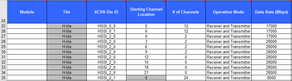
Figure 13. HBM Selections

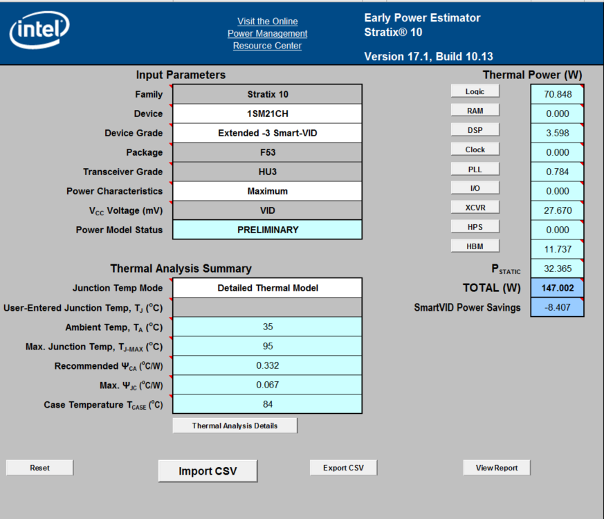
The Main worksheet power values are associated with a function and not necessarily dissipated in the die providing the function. So the Thermal worksheet may show a different value for HBM than the Main worksheet. For thermal analysis, always use the power values in the Thermal worksheet.
Figure 14. EPE Main Worksheet
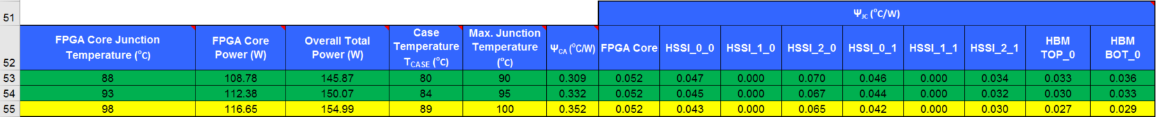
After entering all the design data into the EPE and activating the Thermal worksheet, the following two tables are updated with all the thermal design parameters. For example in this design the case temperature should be kept below 84 °C and the maximum ΨJC of any die is 0.067 °C/W.
Figure 15. EPE Thermal Worksheet
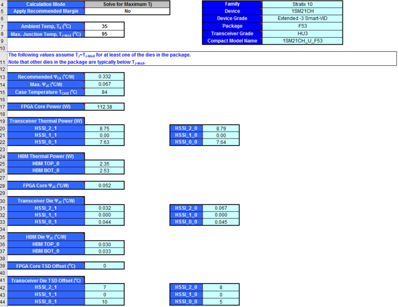
Figure 16. EPE Thermal Worksheet Solution Table